MAINTENANCE
Caution: Wear appropriate personal protective equipment during exposure to hazards.
Potential Hazards: Compressed air and chemical splash, contact, or fumes.
Gear and procedure: May include safety glasses, goggles, face shield, coveralls, apron,
gloves, and ventilation.
1. Soak the pump in a cleaning solution for 1-2 days to break up any hard scaling.
(Solution comprises of a 1:30 of Crystal Simple Green or comparable)
2. After it has soaked, the pump may be removed from the cleaning vat and allowed to drain.
3. Once any excess liquid has been drained from the pump it is ready to be taken apart for
evaluation. Place the pump in a vise with rubber soft jaws, clamping the head and casing
together to ensure neither rotate. Support the other end of the pump so it is horizontal. Use
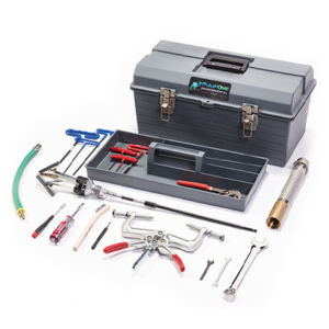
the bottom check valve wrench to remove the bottom check valve from the pump.
4. Use the casing removal tool to remove the casing from the pump. Screw it to the bottom of
the discharge tube, take the pump from the vise, hold it by the casing, and hit the removal
tool on a block of wood or rubber mat.
5. Once the pump has been removed from the casing, spray it down with water to remove any
remaining debris and place the pump back in the vise.
6. Inspect the various parts of the pump for malfunction
A. Check Actuator Bracket for correct placement
B. Ensure Actuator Pins are not protruding from Actuator Rod
C. Check Actuator Rod Spring for damage
D. Ensure Float is not rubbing against Discharge Tube
E. Check Air-In and Exhaust Valves for correct timing and placement
F. Check Magnets for damage
7. Screw a ¼” male air coupler in the air-in side of the pump (in place of air-in hose barb).
Connect to an air-line. Make sure that the air valve seals bubble-tight while the float is in a
neutral position between the actuator stops.
8. Check the float for the correct buoyancy and trip marks. Remark the float if needed: 1.5”
from bottom of float, 2” up from buoyancy level.
9. Float test the pump to ensure the rocker trips up and down at the float markings. Adjust
magnets as needed.
10. Apply a thin film of grease to the inside of the casing ends ¾” deep, and also to the O-rings
on the head and bottom check valve. Insert the pump back into the casing. Press until the
head touches the rim of the casing.
11. Flip the pump over and thread the bottom check valve back onto the discharge tube.
12. Place the pump back into the vise (ensure that the vise is tightened on the head of the pump)
and turn the bottom check valve just until it touches the bottom of the casing. Do not tighten
the valve against the casing.
13. Visit us at pumponellc.com for videos on magnet adjustment, air valve adjustment, and pump
testing procedure.

